Technical Hobby
Web Site
Links
| John
Doran's Technical Hobby Web Site |
Home Links |
| D16/M Minicomputer Page.
Click
on pictures to get larger/higher quality images. |
|
The D16/M is a general-purpose,
stored-program,
single-address, 16-bit digital
computer using two's complement arithmetic. It
manages subroutine calls and interrupts using a memory stack. The
processor may directly address 64K words of memory or I/O.
Its timing and control unit is
microprogrammed (fully horizontal, with a 72-bit control word). As presently configured, the D16 has 73 unique processor instructions. There are eight addressing modes: Implied, Immediate, Direct, Indirect, Post-Incremented Indirect, Direct Indexed, Indirect Indexed, and Post-Incremented Indirect Indexed (see the D16 Instruction Set for details). The machine is implemented in SSI and
MSI
HCMOS integrated
logic and constructed using wire-wrap techniques. It is packaged in a 6U (10.5 inch)
rack-mount
enclosure, and has a 100-pin bus for main
memory (CMOS
SRAM) and peripheral interfaces. Photos and additional details of the D16/M
main memory module and peripheral
interface modules may be found on the separate D16/M Peripherals Page. |
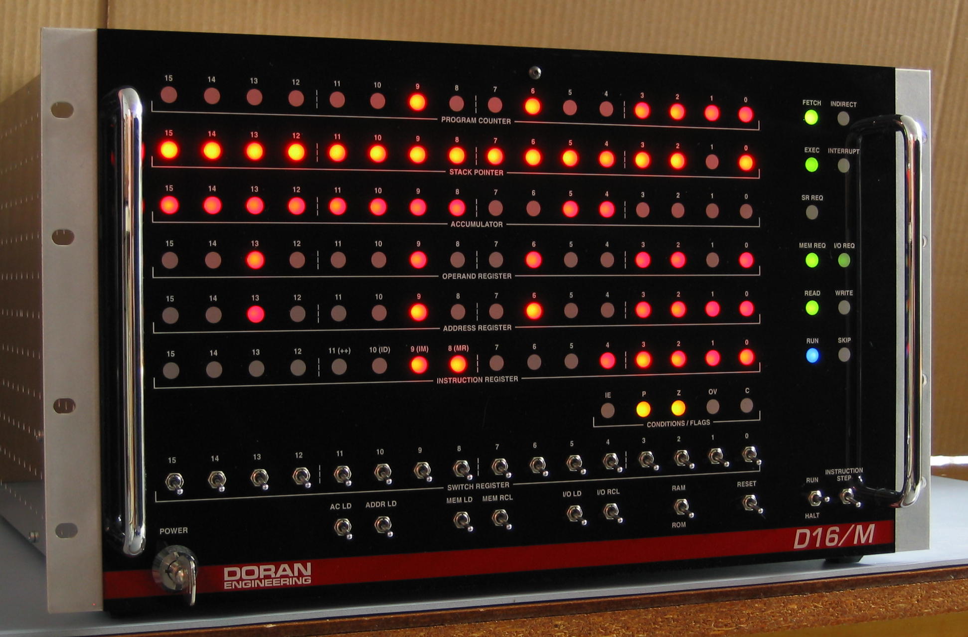 |
« This is a photo of the machine's front panel, showing the register displays, flag and status indicators, and operator controls. A description of the functions of each of the controls and indicators is included in the Documents section below. |
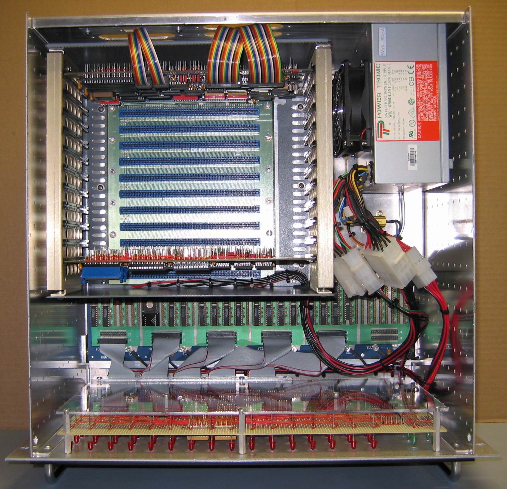 |
« Here is a top view with the cover off. At the top of the photo are the power supply (a PC-type switcher) and the external bus card-cage; at the bottom is the front panel board. The main processor board may be seen in the bottom of the cabinet, connected to the front panel board by nine short ribbon cables. |
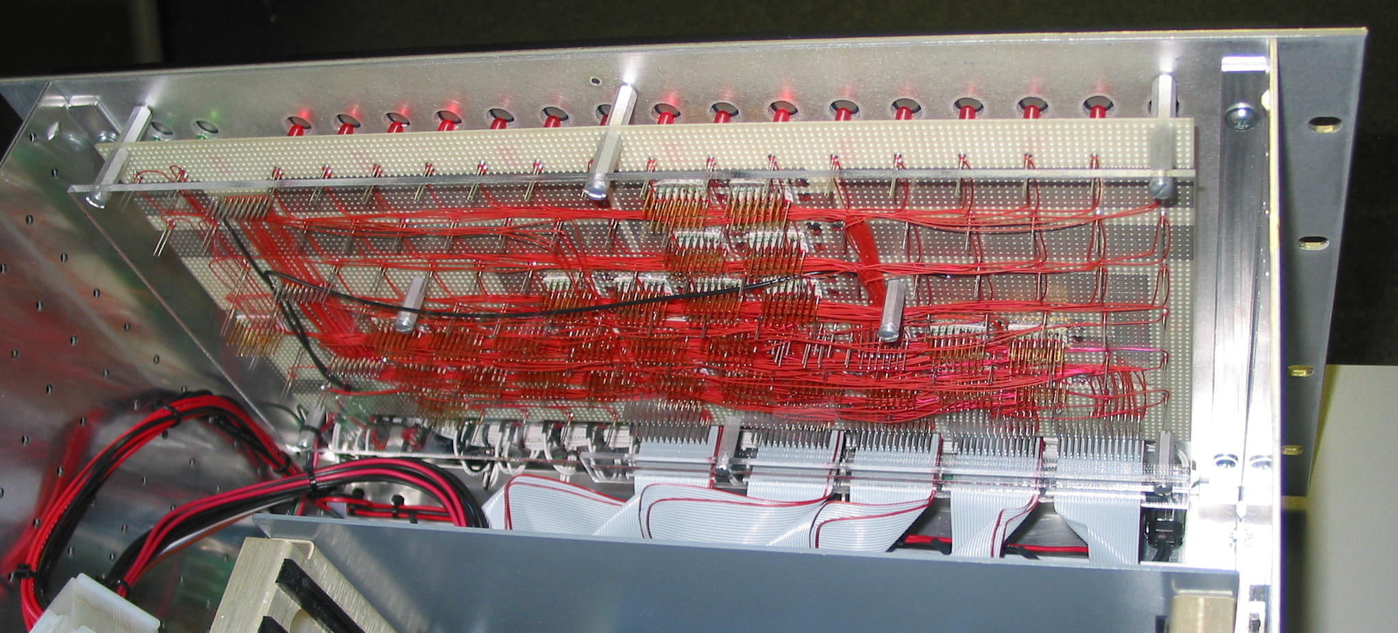 |
« Here is a closer look at the wiring-side of the front panel board. Note the acrylic shroud that protects the board from accidental damage. This view also shows how the LED lamps illuminate the acrylic front panel through holes in the aluminum sub-panel. |
 |
« This photo shows an oblique view of the bus cage and power supply. Again, the main processor board is visible in the bottom of the cabinet; the four hexadecimal readouts at the left side of the board are the microprogram counter register display (used for debugging). The front-most of the two boards in the bus cage is the computer's main memory. |
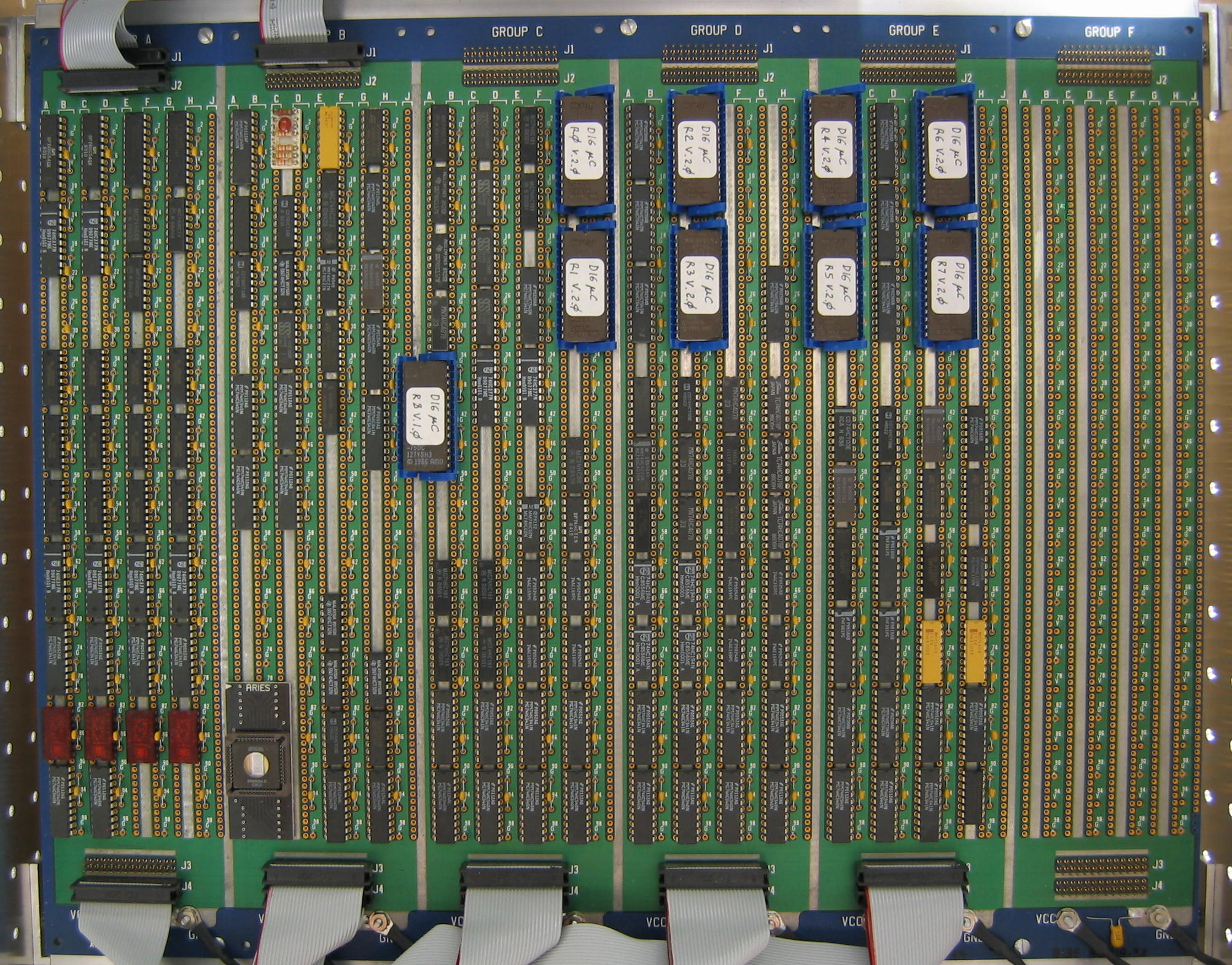 |
« This is a view down onto
the main processor board itself, with the external bus
cage having been tilted up out of the way. The EPROMs in the ZIF
sockets at the upper right are the computer's microprogram store. |
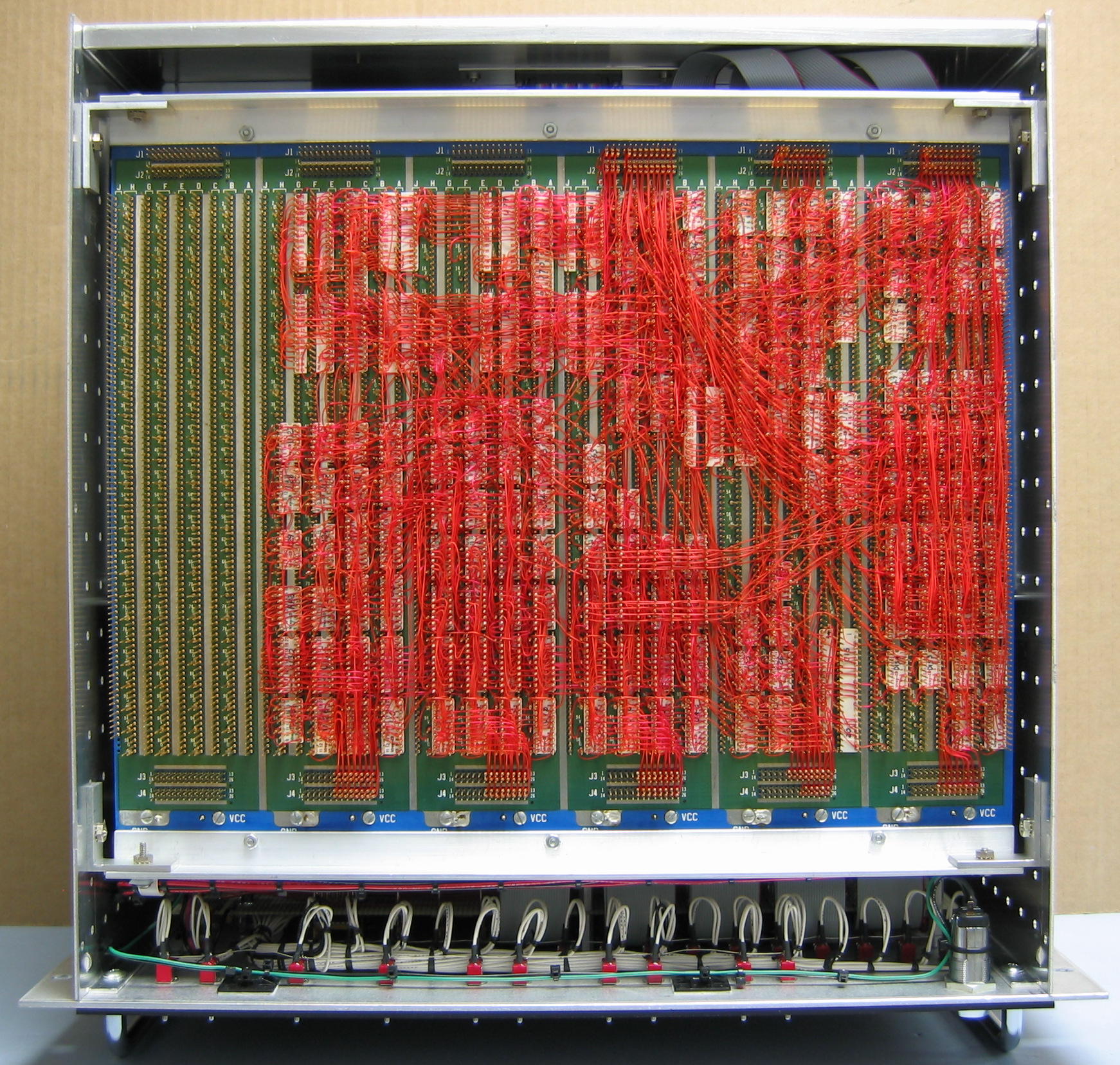 |
« Here is a bottom view
with the cover off. The underside of the main processor board is
just inside the
bottom of the unit, allowing easy access to the wiring. The
circuitry at the bottom of the picture is the front panel switch
wiring. |
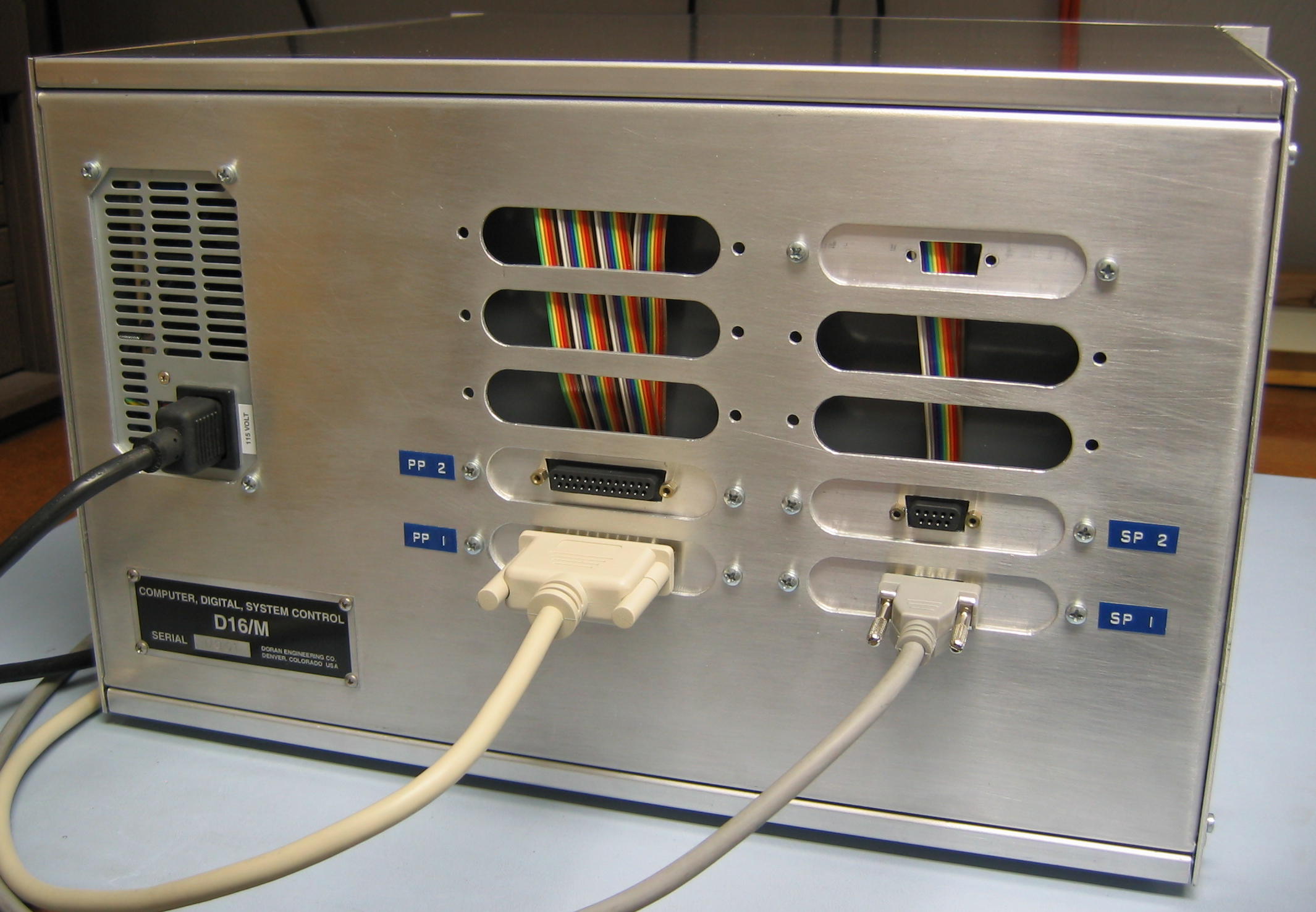 |
« Finally, here is a look at the rear of the cabinet. There are cutouts in the back panel for mounting interface connectors, and a military-style engraved aluminum serial-number plate! |
| The D16/M
documentation follows. All docs are in Adobe PDF format, except
those
specifically indicated otherwise. D16_regs D16 register architecture ("block diagram") D16_instr D16 instruction set. D16_state D16 processor state diagram. D16_ops D16 processor microcode source listing. D16_prog D16 processor microcode ROM contents listing. D16_uinstr D16 processor microcode bit ROM bit functions ("microinstruction set"). D16_uprog_guide Detailed Microprogramming Guide for the D16 processor. D16_bus D16/M external bus connector pinout. D16_TBL (ASCII) D16 Processor function table for CROSS-32 meta-assembler. CPU_SCH Schematic diagram of the D16/M main processor board. PANEL_SCH Schematic diagram of the D16/M front panel board. MEM_SCH Schematic diagram of the D16/M main memory/bus terminator board. 2PULSE Schematic diagram of the switch-debounce Programmable Logic Device. D16_cpubd_layout Component layout for the D16/M main processor board. D16_fpbd_layout Component layout for the D16/M front panel board. D16_fp_art Artwork (graphics) for the D16/M front panel. D16_panel_functions Description of the D16/M front panel controls and indicators. D16_FAQ (HTML) D16 Frequently-Asked Questions. D16_design_notes (HTML) D16 Design and Construction Notes. D16_changes (HTML) Changes and update information. wire_wrap (HTML) A general discussion of wire-wrap construction. |
| Copyright TimeFracture 2004,
2005. |