John Doran's
Technical Hobby
Web Site
Links
|
John Doran's
Technical Hobby
Web Site
|
Home Links |
| Homebrew CO2 Laser Page.
Click
on pictures to get larger/higher quality images. |
|
I built this laser and its power supply in
1980, as my "senior project" at school. I wrote
a
detailed, illustrated report describing its construction
(included in the documentation below). I have made a few changes over the
years. The electrical connections to the laser's electrodes
originally passed out of the tube through the gas tubulations; I
removed these and replaced the original electrodes (as shown in the
report) with longer
lengths of brass tubing that connect directly to the mirror
cells. Also, I re-routed the gas tubing through the base
extrusion. Finally, I have replaced the original 90%-reflective
germanium output coupler (which was just a broken fragment of a larger
mirror!) with a 92%-reflective zinc selenide part. I dusted off the laser after several years of disuse, powered it up, and took these pictures on July 26 and August 1, 2004. |
 |
« This photo shows
the laser loading 25 watts into a firebrick. The electrical
discharge
down the bore of the laser tube is visible on the left. I
measured the laser's output using a Coherent/Molectron handheld
thermopile power meter (not shown). |
 |
« Here is the
whole system, sitting on my parts bench. The large green box at
the
upper left is the laser's power supply. |
 |
« This is a close-up of
the laser's "business" end. It shows the laser tube mount and the
electrical connection to the mirror cell. The
output coupler is just visible inside the output aperture. |
 |
« A look at the
laser's aft end shows how the gas, water, and electrical cabling are
routed through the base and out the back. |
 |
« Here is a side view of
the output end that shows how the electrode is arranged, and how the
mirror cell is attached to the tube. The dark smudge at the end
of the electrode is a metal film sputtered by the electrode onto the
inside of the glass. |
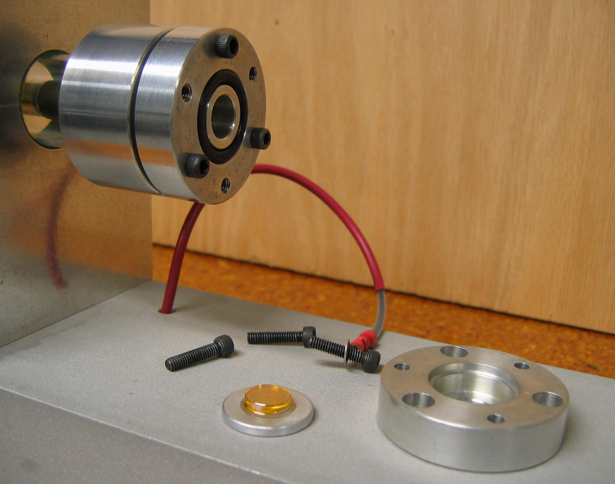 |
« With the output mirror
cell partially disassembled, you can see how the output coupler
is mounted and sealed. The O-ring bears against the bottom of the
mirror carrier, which is held in place by the heavy aluminum end
plate. |
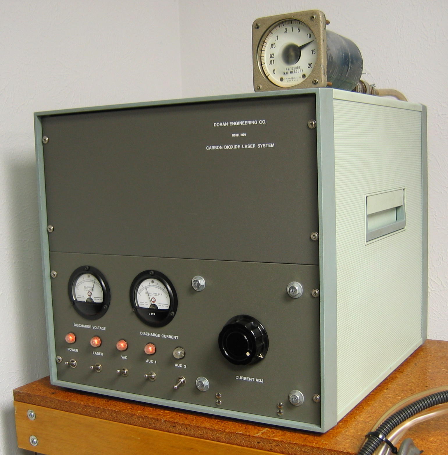 |
« This is the power
supply, with my pressure gauge perched on top of it. It has
analogue meters for measuring discharge voltage and current; and
switched, rear-mounted "convenience outlets" for the gauge and the
vacuum pump. The gauge is an old General Electric "viscosity" instrument calibrated specifically for air, and so its readings of the laser gas pressure are probably too low--the mixture consists mostly of helium. |
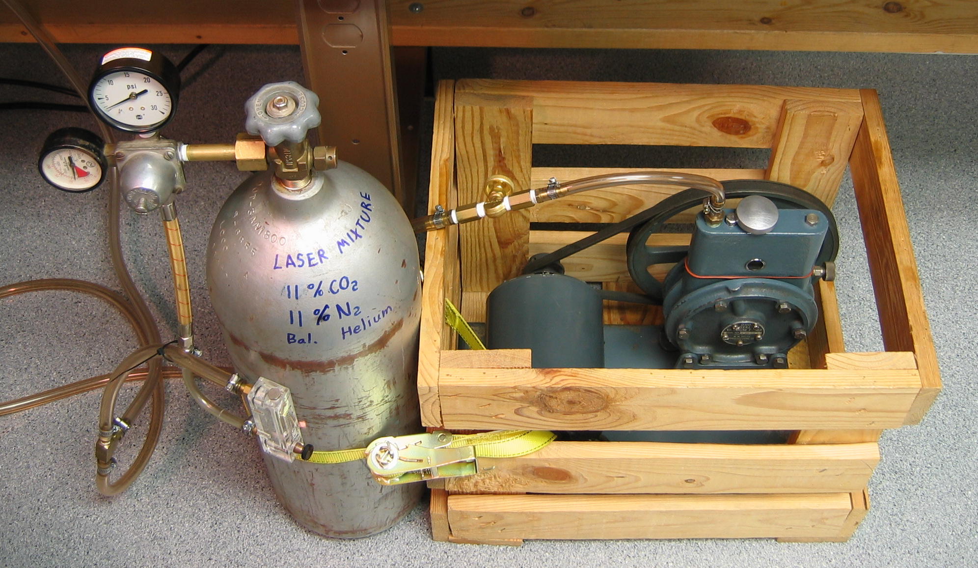 |
« The gas handling system
is simple, consisting of the gas cylinder and regulator, a metering
valve (built into a flowmeter body having insufficient range!), a
throttle valve, and the vacuum pump. |
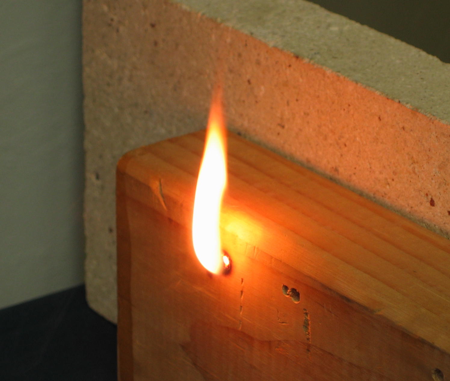 |
« Watch out! A block
of wood, inserted into the laser's beam, bursts instantly into flame... |
| Documentation for the laser
follows. All docs are in Adobe PDF format, except
those
specifically indicated otherwise. laser_report My original report on the laser for EE 4430. It contains drawings of the laser itself, and the schematic diagrams for the power supply. laser_design_notes (HTML) CO2 Laser Design and Construction Notes. warnsign An ANSI-standard CO2 laser warning sign for the lab. |
| Copyright TimeFracture 2004-2009. |